


Blog, Optical Networking, Optical Transceiver
What is Forward Error Correction: Understanding FEC Techniques in Optical Communications

Jun
High-speed optical signal transmission is affected by many factors. Especially in high-speed long-distance transmission, noise, dispersion, nonlinear effects, and Polarization Mode Dispersion (PMD) can all affect optical signal quality. Forward Error Correction (FEC) is an important technology in modern optical communication systems. It detects and corrects bit errors at the receiving side without retransmission. This technology improves data integrity in long-distance high-speed transmission.
This article will explain what FEC is and the important role it plays in optical communications. It will also introduce deployment considerations and application practices.
Table of contents
What is FEC
In optical communication systems, optical signals are generated by lasers and transmitted through optical fibers over long distances. During this process, signals gradually weaken and are affected by dispersion, noise, and device performance limitations. When the receiver converts the optical signal into an electrical signal, some information that originally represented “0” or “1” may be misinterpreted. After PAM4 modulation became widely used, this issue became more obvious. Because PAM4 signals contain four signal levels, the spacing between adjacent levels is much smaller than in traditional NRZ signals, making them more sensitive to noise. The purpose of FEC is to automatically repair these errors before they affect actual services.
Firstly, FEC in optical was derived from the channel coding concept in digital communication systems. The reason for employing FEC in digital communication systems is to prevent errors arising from noise and interference. This technology differs from conventional schemes, in which, upon error detection, the transmitter must retransmit the data. In this system, specific additional codes will be encoded before sending the data. These additional codes will be used for error correction when the data is received.
How FEC Works
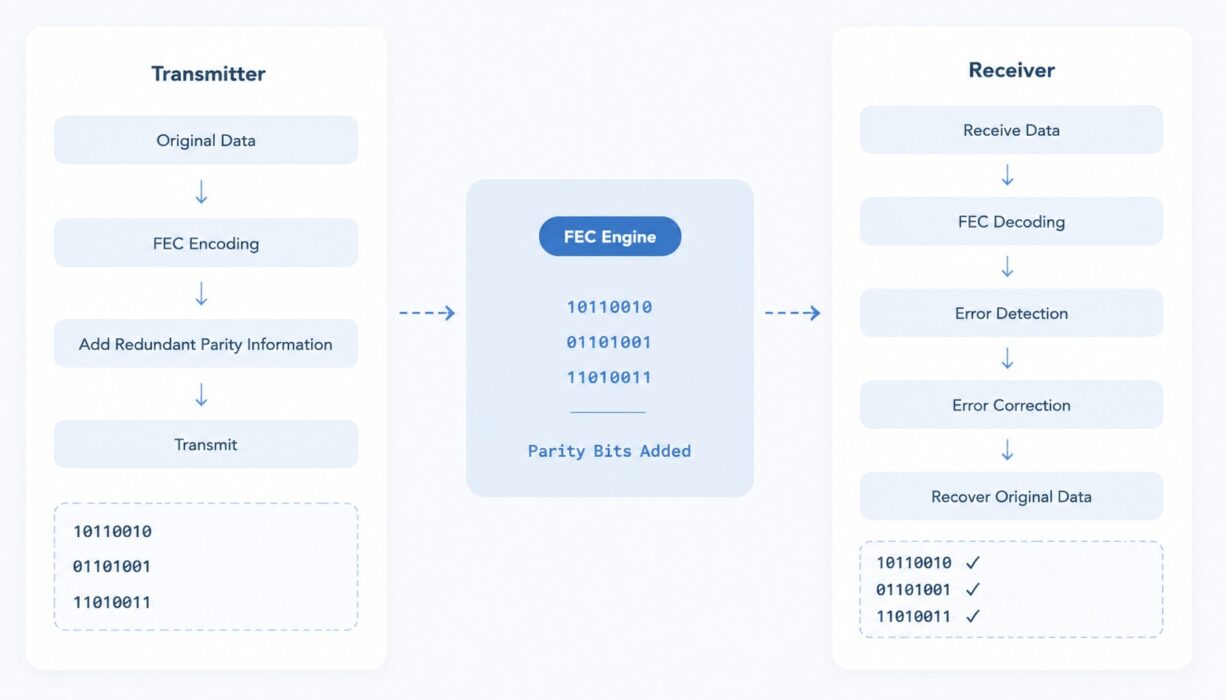
On the transmitting end, the initial input first passes through the FEC Encoder. The encoder manipulates the data using the specific algorithm, producing further parity symbols. The parity symbols, along with the original data, form a new encoded data block referred to as a codeword. The codeword gets transferred using the optical connection.
The decoding algorithm used in the optical FEC Decoder helps identify errors and allows recovery of the original input data. Provided that the number of errors is within the error-correction process’s capabilities, the decoder succeeds in recovering. Consequently, in the presence of transmission noise, the receiver can use the parity data to reconstruct the original input.
Common Ethernet FEC Types and Standards
| FEC Type | Standard Name | Typical Applications |
|---|---|---|
| KR-FEC | RS(528,514) | 25G, 100G NRZ |
| KP-FEC | RS(544,514) | 100G PAM4, 400G, 800G |
| LL-FEC | RS(272,257+1) | Low-Latency Applications |
| SD-FEC | Soft Decision FEC | Long-Haul DWDM Systems |
From the implementation perspective, FEC can be divided into Hard Decision FEC (HD-FEC) and Soft Decision FEC (SD-FEC). Hard Decision FEC corrects errors by directly deciding whether a signal is “0” or “1”. Because the algorithm is relatively simple, it is widely used in Ethernet and data center networks. Soft Decision FEC not only determines whether the signal is “0” or “1”, but also evaluates how confident that decision is. By using this additional information, SD-FEC can provide stronger error correction capability and further increase transmission distance. Therefore, Soft Decision FEC is widely used in long-distance DWDM systems, coherent optical communication systems, and submarine cable systems.
FEC in Optical Communication
Benefits of FEC in Optical Communications
- Real-time high-efficiency operations can rectify the errors on the data signals within seconds.
- Increases the stability of long-distance communication
- Lowers the demands on optical devices, allowing cheaper lasers and receivers to be used
- Standard FEC methods assist in switch interconnections and ensure better transceiver compatibility among various vendors.
- Rectified signals can comply with the needs of PAM4 signaling technology.
Existing Limitations
- FEC introduces additional parity symbols and uses part of the transmission bandwidth. It may also introduce extra latency.
- Additional configuration changes may be required. Both ends of the link must use the same FEC mode. Otherwise, the link may not be established successfully.
Applications in Optical Transceivers
1. Long-distance Optical Fiber Transmission
During transmission over 40km, 80km, or even longer distances, optical signals are affected by various nonlinear effects. As transmission distance increases, the received signal quality gradually decreases, and the bit error rate rises.
By increasing coding gain, FEC allows receivers to recover data correctly at lower signal-to-noise ratios. This means the same optical transceiver can achieve longer transmission distance, or lower-cost optical components can be used at the same distance. Many 100G ER4, 400G LR4, 400G ZR, and DWDM systems rely on FEC for stable long-distance transmission.
Error Compensation in PAM4 Optical Transceivers
Since the 400G era, the optical communication industry has fully entered the PAM4 era. Compared with traditional NRZ signals, PAM4 uses four signal levels to transmit data, doubling the transmission efficiency of a single lane. However, this also significantly reduces eye diagram opening. Because adjacent levels are closer together, the receiver is more likely to make incorrect decisions due to crosstalk. Without FEC protection, PAM4 links often fail to meet the bit-error-rate requirements defined by Ethernet standards.
Reducing Overall Optical Transceiver Cost
With FEC providing error-correction capability, the system can tolerate a higher original bit-error rate (Pre-FEC BER). This allows vendors to use more cost-effective lasers, drivers, and receivers while still meeting the final bit error rate requirements.
The higher the data rate, the more pronounced the reliance on FEC becomes. 25G NRZ typically uses KR-FEC. 100G PAM4 typically uses KP-FEC. 400G DR4, FR4, and LR4 generally all require RS-FEC. 800G DR8, 2×FR4, and FR8 also require RS-FEC support. 1.6T optical modules are expected to continue using higher-gain RS-FEC solutions. Simply put, virtually all high-speed optical modules that use PAM4 modulation rely on FEC.
-
Generic OSFP-800G-DR8 Compatible 800G 2xDR4/DR8 OSFP Finned Top 1310nm 500m Dual MPO-12/APC Transceiver
US$ 899.00 (Excl. VAT) -

Generic Compatible 100G QSFP28 SR4 850nm 100m Transceiver
US$ 29.90 (Excl. VAT) -

Generic Compatible 25G SFP28 SR 850nm 100m Transceiver
US$ 15.00 (Excl. VAT) -

Generic Compatible 100G QSFP28 LR4 10km Transceiver
US$ 169.00 (Excl. VAT)
FEC Deployment on Switches
When connecting different switches, in addition to selecting optical transceivers compatible with the corresponding vendor, switch configuration is also important. FEC is one of those configurations. Different switches may use different default FEC settings. FEC deployment requires both ends of the link to use matching configurations. If one side enables RS-FEC while the other side disables FEC, the link usually cannot be established successfully. In this case, manual configuration changes are required. Cisco switches can be used as an example.
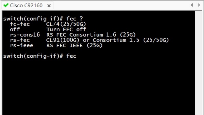
When the required FEC type cannot be confirmed, FEC can be disabled on both sides for lower-speed links. For 400G and 800G networks, it is recommended to use the RS-FEC scheme defined by IEEE standards to achieve the best compatibility.
FAQ
#1 Why does PAM4 require FEC?
Because the PAM4 eye diagram height is about one-third of that of NRZ, it is more sensitive to noise. Without FEC, it is difficult to achieve the target bit error rate.
#2 Must both ends use the same FEC type?
Yes. Otherwise, the link may fail to establish or may experience a large number of bit errors.
#3 Can FEC completely eliminate bit errors?
No. FEC can only correct errors within its designed correction capability. Errors beyond that limit can still occur.
#4 Does FEC increase latency?
Yes. It adds a small amount of encoding and decoding latency, but this is usually much smaller than the latency caused by retransmission mechanisms.
#5 Do 800G optical transceivers always require FEC?
Most 800G PAM4 optical transceivers require FEC support.
Conclusion
Optical FEC is used to guarantee quality and minimize the effect of noise on signal transmission. With increasing demands on network bandwidth and transmission volume, it is essential to implement measures to improve transmission stability and reliability, especially over long distances. From implementing 25G Ethernet networks to scaling up to 800G networks, one can benefit from the proper use of FEC standards.
Read more
- What is CDR? A Beginner’s Guide to Clock Data Recovery
- dB vs dBm: Understanding the Difference in Fiber Optic Measurement
- What Is Optical Return Loss: A Beginner’s Guide