


Blog
What is CDR? A Beginner’s Guide to Clock Data Recovery

May
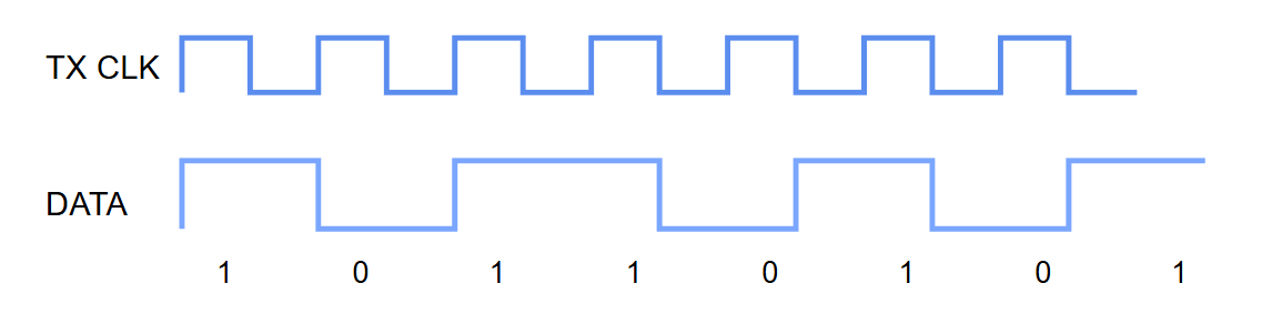
In high-speed digital communication such as Ethernet, many systems use asynchronous communication. This implies that data is sent without an independent clock signal. Although this allows for saving channels, a clock signal must still be recovered from the received data. The accuracy and correctness of received data in such a scenario is where CDR(Clock Data Recovery) comes into play.
What is CDR
CDR (Clock Data Recovery) means clock and data recovery. In modern high-speed serial communication, data is usually transmitted as a continuous bit stream without a dedicated clock line. It results in the reduction of the number of pins required, the complexity of the printed circuit board, and increases the level of system integration. However, what this implies is that the receiver will need to retrieve clock information from the transmitted data itself. If this is not done, there is no way for the receiver to tell whether the data being received is 0 or 1.
Why High-Speed Signals Need It
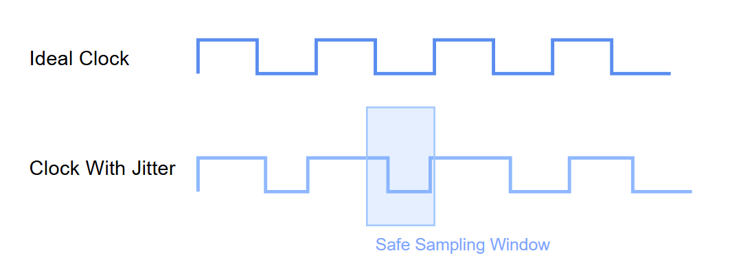
As data rates increase, the sampling window becomes smaller. When speeds move from 10G to 112G PAM4 or even 224G, the duration of each bit becomes only a few picoseconds. At this point, even very small clock offsets, jitter, or noise can cause sampling errors at the receiver, leading to bit errors. Because of this, modern high-speed communication systems must continuously recover and adjust the synchronization relationship between clock and data. And CDR is one of the key technologies responsible for this process.
How Does CDR Work
When the receiver receives a continuous stream of high-speed data signals, the first step of CDR is to observe the transition positions inside the input signal. These are the edges where 0 and 1 change. By detecting these transitions, the receiver can estimate the approximate clock frequency of the transmitting side.
The next step involves using a PLL (Phase-Locked Loop) within the CDR circuit. It is used to generate a clock signal and compare it with the received data stream. In case there is a mismatch between the recovered clock and the input data. The PLL will generate a feedback error signal. The phase-locked loop receives two signals: the input data stream and the recovered clock, and continuously adjusts its output until the clock’s phase and frequency match those of the input data stream. CDR first detects the transition edges inside incoming data, then continuously adjusts the recovered clock through PLL feedback.
This is then followed by further fine-tuning of the recovered clock. The high-speed link can never be perfectly stable due to factors such as PCB attenuation, EMI, noise, and variations in temperature, among others, which may influence the signal integrity. As such, the CDR has to constantly follow any changes in the signal in order to fine-tune the clock recovery. In doing so, however, any instantaneous changes in the recovered clock could lead to instability in the clocking, or worse still, a loss of lock.
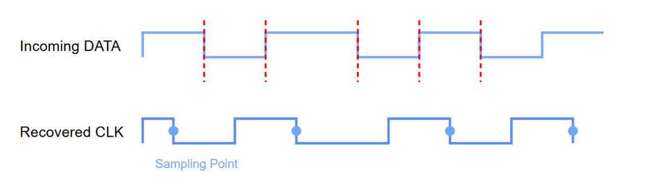
CDR is also responsible for handling jitter in high-speed communication channels. This allows the device to synchronize the system with the incoming stream. Even if there is some form of variation in the timing of the signal. Lastly, after the successful locking of the input stream by the PLL, the CDR generates a recovered clock that is in sync with the input.
CDR Usually Exists Where
In the former cases, a CDR might have been implemented as an independent device such as a standalone CDR Chip or a retimer chip. In today’s high-speed communication systems, CDR implementations are usually found in DSPs, Retimers, and SerDes.
- Standalone CDR Chip
Standalone CDR chips were commonly used in earlier high-speed systems or special interfaces and mainly focused on clock recovery and data synchronization. - DSP with Integrated CDR
Many modern DSPs already integrate Clock Data Recovery functionality. Besides clock recovery, DSPs also perform Equalization, FEC, and Retiming. - Retimer with CDR
Retimer chips usually include CDR internally. They first recover the clock through Clock Data Recovery, then reshape and retransmit the high-speed signal. - SerDes Internal CDR
Modern switch ASICs and high-speed SerDes devices usually integrate internal CDR modules.
Applications of Clock Data Recovery
The CDR technique plays an integral part in today’s modern optical communication systems. For high-speed data synchronization, CDR is widely used in optical transceivers, switches, routers, and interconnections in data centers. For 400G, 800G, and future 1.6T links, clock recovery capability has become a critical parameter for maintaining stable links. Nonetheless, CDR technology is widely used beyond optical communications.
-
Generic OSFP-800G-DR8 Compatible 800G 2xDR4/DR8 OSFP Finned Top 1310nm 500m Dual MPO-12/APC Transceiver
US$ 899.00 (Excl. VAT) -
0.5~2m Generic QDD-800G-DAC Compatible 800G QSFP-DD DAC Cable
Price range: US$ 119.00 through US$ 199.00 (Excl. VAT) -
0.5~2m Generic OSFP-800G-DAC Compatible 800G OSFP Finned Top DAC Cable
Price range: US$ 99.00 through US$ 159.00 (Excl. VAT) -
Generic QSFPDD-400G-SR8 Compatible 400GBASE-SR8 QSFP-DD 850nm 100m Transceiver
US$ 139.00 (Excl. VAT)
- Telecommunications and Networking: Telecommunication systems and networking devices have high-speed data streams that need to be synchronized. CDR is used in order to achieve synchronization between devices and reduce the bit error rate and packet loss.
- Data Storage System: Storage media operating at high speeds, like SATA, SAS, and Storage Area Network, use clock data recovery techniques to enable reading/writing synchronization.
- High-Speed Data Interface
High-speed data interfaces such as PCI Express, USB, and high-speed backplanes require CDR to perform synchronization at high speed. - Optical Communication: Optical fiber communications utilize CDR to recover the clock in high-speed optical signaling.
- Audio & Video Application: Clock data recovery technique is required in audio/video interfaces such as HDMI and SDI to ensure synchronization of data.
- Satellite Communication: Long-distance transmission in satellite communications causes some delays and jitter. Clock recovery becomes necessary to recover the signal.
- Radar & Sensor System: Synchronization is extremely vital in radar systems. Clock Data Recovery works on high-speed sampled data for synchronization.
FAQ
#1 Is Clock Data Recovery a chip or a function?
Both. Earlier systems often used standalone CDR chips, while modern high-speed systems usually integrate CDR into DSPs, Retimers, or SerDes.
#2 Does every optical module use CDR?
Not always. Some fully linear optics may reduce or remove certain retiming functions, but most high-speed modules still rely on Clock Data Recovery in some form.
#3 Why is CDR important in high-speed communication?
Because modern serial communication usually does not include a separate clock line. CDR helps recover timing information from incoming data.
#4 Does every SFP module use CDR?
Not necessarily. Earlier low-speed SFP modules, such as 1G SFP SR, LX, or ZX, and even some 10G SFP+ modules, usually do not include dedicated CDR circuits inside the module.
#5 Do 400G and 800G optical modules rely on CDR?
Yes. Modern high-speed optical modules such as 400G QSFP-DD and 800G OSFP usually rely heavily on CDR and retiming technologies.
#6 Do most 10G SFP+ modules include CDR?
Not always. In fact, many standard 10G SFP+ modules do not include full standalone CDR circuits inside the module. However, some enhanced or telecom-grade 10G SFP+ modules may still include additional CDR or signal conditioning functions.
Conclusion
The smooth flow of high-speed signals involves several factors, chip types, and functionality. CDR (Clock Data Recovery) is one of them. Understanding the significance of these technologies can be highly beneficial for choosing an optical module and for study purposes.
Read more
- What Is Optical Return Loss: A Beginner’s Guide
- What Is Digital Diagnostic Monitoring? A Complete Guide to SFP DDM/DOM
- LPO vs LRO vs CPO vs NPO Optics: Understanding The Difference