In digital video, in order to facilitate the long-distance transmission of the digital signal, the parallel data is converted into serial data, which is transmitted to the receiving end through a cable or optical fiber. SDI is the abbreviation for this serial data interface. In the high-speed SDI signal transmission and conversion process, because of the performance of hardware equipment and installation level of different, resulting in SDI signal quality degradation, resulting in high-definition video signal reception error. It is often necessary to test the SDI signal and find the possible causes of the problem based on the test results, thus ensuring the performance of each link in the HD system.
High-definition video signals are transmitted using analog signals before the SDI signal appears. The analog signals are very easy to degrade in the process of transmission and conversion, and the waveform sampling is usually carried out by the high-speed oscilloscope. Generally, the indicators to be tested include color stripe amplitude, synchronization amplitude and time, noise, frequency response, Multi-Wave Group, nonlinearity, channel delay, instantaneous characteristics, etc.
Figure 1 analog video signal test waveform
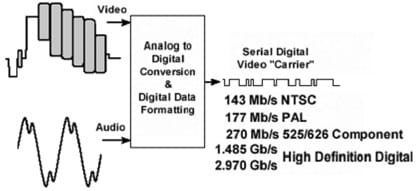
The SDI signal uses a single coaxial cable to transmit all digital video and audio information using a modular conversion and high speed serial coding technique. Because SDI is a digital signal, the principle and characteristics of the signal are different from the analog video signal, so the focus of the SDI signal testing is different from the analog video signal test. Several key features of the SDI signal are as follows: level amplitude, jitter, Rise/fall time.
Figure 2 Schematic diagram of SDI signal generation
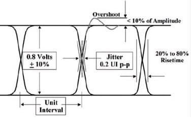
According to SMPTE 259M, SMPTE 292M, SMPTE 424M standards, SD-SDI, HD-SDI, 3G-SDI signal quality standards (including amplitude, overshoot, rise/fall time, jitter time, jitter arrangement, etc.) are different. Furthermore, the SDI and 3G-SDI high-speed signals require dozens of to hundreds of PS magnitude for the rise/fall time.
Figure 3 SDI digital signal characteristics
The above indicators are generally tested by the eye and jitter display tools of the waveform test instrument.
Eye Diagram and Jitter Test
Eye diagram and jitter test are two important tools for SDI testing.
Figure 4 Eye diagram
The jitter test reflects the random noise through the horizontal display line through an enlarged graphic display. Jitter includes two types: time jitter and queue jitter.
Time jitter: The signal transition position at a rate greater than a specified frequency (typically 10 Hz).
Queue Jitter: Changes the signal jump position relative to the clock extracted from the signal.
System Margin Test
The high-speed SDI signal is characterized by a potential problem on the system or a decline in the reliability of the system, but there is no change in its BER monitoring, which means that we cannot find this potential problem. Therefore, it is necessary to test the system reliability and system margin through special experiments to ensure the safe operation of the system. Common system margin test methods are:
Level amplitude change test: adjust the input level amplitude, the determination of the receiving unit equalizer capacity.
Noise test: SDI signal to add a certain amount of noise to confirm whether there is an error.
Jitter test: SDI signal attached to shake, to confirm whether there is an error.
CRC error Test: CRC is an error check measure adopted by SDI. At the receiving end, the CRC that is recalculated is compared to the CRC inserted in the message code to determine the transmission error.
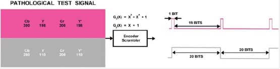
Pathological Signal Test
SDI Pathological signal is a special information code to test SDI performance. The special information code creates a worst-case data for low-frequency energy, and after scrambling, there are two special cases of data.
In one case, the luminance signal is set to 198H and the two color difference signals are set to 300H. After the encoder scrambling code, generate a 1-bit high and 19-bit low special NRZI non-return-zero reverse code. Provides a higher DC component to test the ability of the receiving system to simulate and transmit signal processing. This test signal appears on the top of an image with magenta shadows.
In the other case, the luminance signal is set to 110H and the two color difference signals are set to 200H. After the encoder scrambling code, generate 20-bit high and 20-bit low special NRZI non-return zero reverse code. Provides a minimum number of “0” spans for clock extraction to monitor device phase-locked loop performance. This test signal appears in a gray shade on the lower part of an image.
The SDI receiving device should be able to handle both test signals correctly.
SDI Physical Layer Problem Diagnosis
By analyzing the eye diagram and jitter waveform, the problem of SDI signal transmission can be judged roughly. The main fault cause types are as follows:
Signal Amplitude: signal amplitude is very important because it is closely related to noise. Because the receiver adopts equalizer for high-frequency compensation, when the signal arrives, the incorrect amplitude of the sending end may lead to incorrect equalization, which causes the signal distortion.
Rise/Fall Time: Incorrect rise/fall time can cause signal distortion, such as ringing and overshoot.
Overshoot: Overshoot is usually the result of incorrect rising time, which is probably caused by the impedance discontinuity or by the poor return loss at the receiving and sending ends.
Random Jitter: caused by the equipment thermal noise or impact noise, with infinite Gaussian distribution characteristics. Therefore, jitter amplitude is usually measured using the jitter RMS value. In addition, Peak peak jitter, although the probability is small, can be used to characterize the location of the fault.
Deterministic Jitter: has periodic characteristics that may be generated by a fixed device in the system. Possible sources of jitter include switching power supply, rise and fall time difference generated by the duty cycle, synchronous lock caused by the main clock changes, and string conversion processing, the cable frequency response.
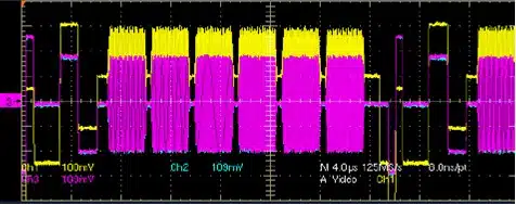
Fault diagnosis is a combination of theory and experience. In the actual test application, it is necessary to combine the actual situation of the system, take a variety of test methods, and analyze and reason the specific test data in order to accurately locate the signal transmission process may be faulted reason. Here are a few typical fault signal test results.
Conclusion
SDI high-definition video system in a good equipment, high-quality cable and the correct installation of the premise, still need to conduct professional performance testing in order to ensure SDI high-speed video data flow continuity and correctness. Must be equipped with a professional signal generator and waveform monitor, through the eye diagram and jitter and other means of measurement, the system installation and system work to provide continuous performance monitoring, to identify problems and diagnostic problems. Eye diagram analysis provides a visualized SDI physical layer health check that signals intuitive “bright eyes” to ensure that back-end devices can easily restore clocks and data. In addition, the jitter waveform can be further continuous monitoring of the signal, so as to achieve the purpose of in-depth diagnosis of fault causes.
Optcore
1 thoughts on “How to test the SDI signal?”
Bill says:
I read your article and have the following comments.
A CRC is generated by the division of the message by a short sequence of bits from 1 to 64. 32 is a common implementation.There will be a remainder from this division which is appended to the message. On reception the new Message with the remainder is divided is by the CRC if it divides exactly ( no remainder ) then the message has a high probability of being OK. The CRC is not calculated and compared to your paper states.
The basic code is NRZ so has to be encoded to allow transmission over a link.
The difference between SDI and ethernet is SDI scrambles the data, the result is the data rate remains the same, but it requires the system to have a low frequency cut off due to codes (pathological) which are generated.Ethernet takes each byte (8 bits) and converts this to 10 bits not using codes with a low number of transitions. The result is a narrower bandwidth and it is easier to decode. On the downside, the data rate goes up by 25%. Ethernet does also scramble, but only on copper to reduce EMC.
SFPs for data or video are basically the same, but the video requires a lower bandwidth.
I wrote some programs ( a long time ago, ) which could do a Fourier analysis of a pattern, then bandwidth limit this. it could then work out the time errors on the eye. I was at that time I was designing disc channels, there is a great similarity between this and fibre.

 Español


I read your article and have the following comments.
A CRC is generated by the division of the message by a short sequence of bits from 1 to 64. 32 is a common implementation.There will be a remainder from this division which is appended to the message. On reception the new Message with the remainder is divided is by the CRC if it divides exactly ( no remainder ) then the message has a high probability of being OK. The CRC is not calculated and compared to your paper states.
The basic code is NRZ so has to be encoded to allow transmission over a link.
The difference between SDI and ethernet is SDI scrambles the data, the result is the data rate remains the same, but it requires the system to have a low frequency cut off due to codes (pathological) which are generated.Ethernet takes each byte (8 bits) and converts this to 10 bits not using codes with a low number of transitions. The result is a narrower bandwidth and it is easier to decode. On the downside, the data rate goes up by 25%. Ethernet does also scramble, but only on copper to reduce EMC.
SFPs for data or video are basically the same, but the video requires a lower bandwidth.
I wrote some programs ( a long time ago, ) which could do a Fourier analysis of a pattern, then bandwidth limit this. it could then work out the time errors on the eye. I was at that time I was designing disc channels, there is a great similarity between this and fibre.