


Blog, Optical Transceiver
What Is an Optical Transceiver IC? A Simple Guide For Beginners

Jul
Initial Published: May 1, 2017
Optical transceivers have become a central component of modern networks and data centers. However, many people are still unfamiliar with the optical transceiver IC, the core component hidden inside the module. As the core component of an optical module, the transceiver IC is akin to the CPU of a computer, facilitating the conversion and processing of electrical and optical signals. As part of our series of tutorials, this article focuses on the optical module chip and provides a brief introduction to its basics, aiming to offer practical help to beginners.
First, let’s understand what an optical transceiver IC is.
What is an optical transceiver IC?
Optical transceiver ICs are tiny integrated circuits or semiconductor chips integrated inside a similar SFP, QSFP, or QSFP28. Its role is to perform core optoelectronic signal conversion and signal processing functions. Without these chips, no optical module can work correctly. Hence, the chip is a core component of an optical transceiver.
You can imagine the optical module as a complete “translator”; its core task is to equipment (such as switches, routers, servers, and network cards) issued by the “electronic language” (electrical signals) into a high-speed transmission in the fiber optic. The core task is to translate the “electronic language” (electrical signals) from devices (such as switches, routers, servers, and network cards) into the “optical language” (optical signals) that can be transmitted at high speed in the optical fiber, and, in turn, to translate the “optical language” received from the optical fiber back into the “electronic language” that the device can understand.
The transceiver IC is the core of the device, the most sophisticated “brain” and “sensory organs,” responsible for implementing the most critical, lowest-level translation and processing work.
What are the categories of transceiver ICs?
Optical module chips can typically be categorized into two types: Electrical chips and optical chips.
Electrical chips usually process, amplify, shape, and control the electrical signals generated by lasers and detectors to ensure the performance and stability of data transmission.
Optical chips, on the other hand, focus on the mutual conversion of optoelectronic signals. In this article, we mainly discuss the electrical chip.
We usually classify the optical module electrical chip into the following two categories:
#1. Laser Diode Driver (LD)
LDD receives data commands in the form of electrical signals from host devices, such as switches, and then accurately adjusts the size of the current to drive the laser, emitting light signals of different intensities. Therefore, LDD not only controls when the laser emits light and when it goes off (switch), but also controls the intensity of the light emitted to ensure that the light signals can accurately and precisely transmit data.
Generally speaking, according to the different types of lasers, we can categorize Laser Diode Driver into:
- VCSEL Driver ICs
- FP Driver ICs
- DFB Driver ICs
- EML Driver ICs
#2. Transimpedance amplifiers (TIAs)
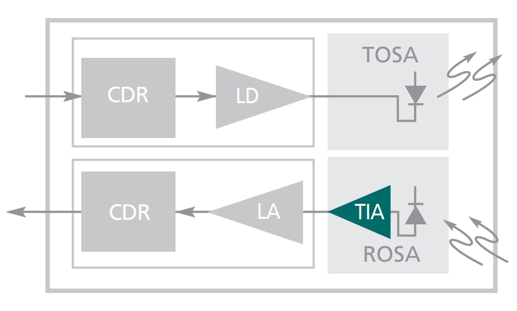
As shown in the previous figure, the Transimpedance Amplifier is a key electrical chip located at the back of the receiver side of the optical module. It is responsible for converting the weak current signal from the photodetector into a voltage signal and amplifying it initially to provide the subsequent Limiting Amplifier with a preliminarily organized electrical signal.
However, many chip manufacturers have now integrated the TIA function and Limiting Amplifier into the same chip, which has improved integration and reduced cost.
#3. Optical Limiting Amplifier (LA)
In an optical transceiver, the Limiting Amplifier is located behind the Transimpedance Amplifier. It is responsible for amplifying and processing the signal initially processed by the TIA into a standard, equal-amplitude electrical signal, providing a stable voltage signal to the CDR and judgment circuit. In high-speed modules, the Limiting Amplifier is typically integrated with the TIA or CDR, and Limiting Amplifier ICs are available from manufacturers such as Maxim, Semtech, Analog Devices, MACOM, and others.
FAQs
Q: Which transceiver IC is OPTCORE SFP use?
Our SFP utilizes the IC from a leading brand, similar to the IC used in SFP fiber transceivers, which typically use a Semtech IC. In contrast, copper SFPs use a Marvell IC.
Final Words
Although it is positioned behind the transceiver, the IC plays a crucial role in the optical-electronic transform function. Now, have you understood its basics, impact, and types? If you have any other questions, leave a message below.
Read More:
- What is Optical Transceiver: A Beginner Guide
- What is SFP Module? An Ultimate Guide
- What Is Digital Diagnostic Monitoring? A Complete Guide to SFP DDM/DOM
Sir
Kindly help me with tutorials and video that shows how to create a diffuse mode optical transceiver on an empty subtrate pcb board
with mention on all the component used so i can make one at home