100G Ethernet is currently increasing, but what does 100G Ethernet actually mean? CFP, CXP, QSFP28, 10x10G, 4x25G, SR4, LR4, FEC, non-FEC… Various names will come out. We will delve into this article and discuss that combination and what is actually applied in this area.
100G Cabling + Connector
100G cabling and connectors are extremely simple. The simplest idea about this is nothing about 100G LR.
LC/SC Long distance 100G LR4/LR10
The cabling is much simpler than the 100G optical transceivers. The real change to 100G LR4/LR10 is that the optical transceiver divides lanes based on light wavelengths (instead of physically separating the fibers). The 100G single-mode SC or LC Connector matches the other data rate of the 1G/10G/40G. The figure1 is an example of a 100G single-mode cable with duplex LC and duplex SC connectors. The maximum transmission distance is 10km in 100G LR4 and is 40km in 100G ER4.
MPO24 Short Range 100G SR10
MPO24 fiber cabling is primarily used for CXP HPC clusters for 100G SR10 connectivity. There are 24 separate fibers that make this cable manufacturing cost a little expensive. Almost rare to find this kind of cable, the 100G SR10 standard will gradually disappear and superseded to 100G SR4. It would be a bad idea to make some kind of investment in this format.
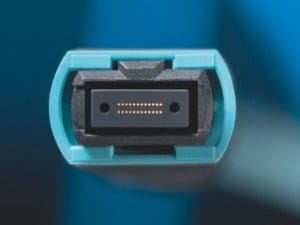
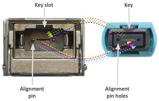
MPO12 short-Haul 100G SR4 – Winner
100G short distance MPO12 fiber cabling is winning. Since it matches exactly the 40G SR4 connector and cabling, the total amount of 100G overall may be slightly higher, but you can update the cabling and patch panels to 40G MPO12. And if that 100G price set goes down, if you had bought a dual mode 40 G / 100 G switch, all you need to do is update that optical transceiver to 100G.
100G Protocol
The protocol for 100G is somewhat confusing. The candidates are SR10, LR10, SR4, LR4, SR4 FEC, LR4 FEC, which makes things complicated. All of these protocols provide a receive / transmit Ethernet port with a data transfer rate of 100Gbps and a packet transfer rate of 148.88 Mpps. But how each protocol is encoded and the last bit comes down that pipe. There are many differences as to how it actually looks. Let’s dig into the various protocols at a higher level.
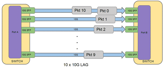
10x10G lanes
Using 10x10g lanes is the easiest way to achieve a 100gbps connection. The first thing you need to clarify is “100G LR10/SR10 = 10 x 10G lag Connection”. The protocol is significantly different.
The above shows what a typical set of lags is like. In principle, this links N links between switches into a single virtual port. The data transmission flows over a standard 10GBASE-SR/LR, but logically it is a virtually 100G port. In this case, for each connection at the bottom, it is a round-robin scheduling packet. The problem here is that the receiving packet can arrive abnormally. Imagine a packet of 1500 B in lane 0 and a packet of 64 B in lane 1. The last byte of 64B will arrive before the last byte of the 1500B packet. The LAG protocol has a way to solve this, but when talking about 100 G generally it does not mean a 10 x 10 G LAG connection.
Next, we will address the true 100G SR10 / LR10 interface. It should be clear from the chart below that “100G SR10 = 10 x 10 G SR LAG link”.
As can be seen in the figure above, the packets are striped across all lanes, especially chunks encoded in 64b / 66b, so there is no problem with ordering. The 100G protocol includes lane deskew using alignment markers. This means that the receiver can correctly align the bits before the packet is rebuilt and sent to the MAC. It also includes the BIP 8 protocol which provides error detection (but not correction) built into that protocol.
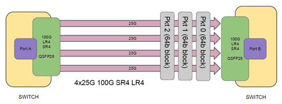
4x25G lanes
Next, we will talk about SR4 / LR4. It is 4 lanes of 25 G each. More precisely because of the encoding overhead, it will be 4 x 25.78125 GHz. It also stripes packets to 64b / 66b blocks before sending all connections, including BIP8 error detection (Note: error detection is not correct). However there is a habit here, there are actually two different standards for 4 x 25 G connection. IEEE 802.3 ba and IEEE 802.3 bm.
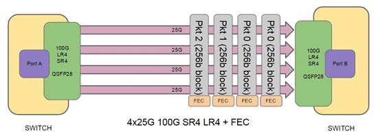
4x25G + FEC
And finally, the industry is concentrated 100G QSFP28 4 x 25 G + FEC. The difference between 802.3ba and 802.3bm is FEC (Forward Error Correction). This changes the stripe size from 64b to 256b and adds a parity block for Reed-Solomon error correction. It is very similar to the way ECC RAM works and uses similar calculations but uses slightly different parameters. Let’s consider that as an ECC serial link. Therefore, with 802.3bm, its receiver can not only detect bit errors but also corrects bit errors and can greatly improve the quality of that link.
Summary
In our opinion, QSFP28 SR4 / LR4 + FEC will be the dominant 100G standard. All switch vendors support FEC and we are convinced that FEC will be available on all 100 G links in its default state, although it is not essential for shorter distance SR4 or LR4. The QSFP28 transceiver is improved in terms of availability and pricing while moving the switch vendor to a single-port, multi-mode 40G/56G/100G QSFP/QSFP28 physical cage.
The breakup of 100G Ethernet is finally starting to converge. It takes a long time to get here, and every person enjoys a 100Gbps network at a reasonable price, so the only remaining challenge is lowering the cost.


 The cabling is much simpler than the 100G optical transceivers. The real change to 100G LR4/LR10 is that the optical transceiver divides lanes based on light wavelengths (instead of physically separating the fibers). The 100G single-mode SC or LC Connector matches the other data rate of the 1G/10G/40G. The figure1 is an example of a 100G single-mode cable with duplex LC and duplex SC connectors. The maximum transmission distance is 10km in 100G LR4 and is 40km in 100G ER4.