


Blog
What is TX Power and RX Power for SFP Module

Jan
In optical communication systems, the transmit power and receive power of an optical transceiver are among the key indicators used to evaluate link quality and module operating status. They play an important role during new link deployment, compatibility testing, and link troubleshooting. A clear understanding of TX Power and RX Power can reduce your confusion during network testing and daily operations.
What Are TX Power and RX Power of SFP?
TX Power (Transmit Optical Power)
The optical signal power emitted from the transmit port of an SFP transceiver. It reflects the signal strength generated by the module under current operating conditions.
RX Power (Receive Optical Power)
The actual optical signal power received by the SFP transceiver. This value reflects the signal strength arriving at the receiver after transmission through the fiber link.
How to Check Optical Power of SFP?
1. Optical Power Meter
A direct and convenient measurement tool that measures the actual optical power at the fiber end face. During testing, connect the patch cord to the transmit or receive port of the SFP transceiver. Engineers commonly use this method for on-site testing and verification.
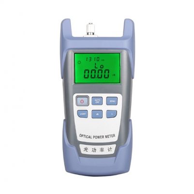
Figure 1: Optical Power Meter
2. Switch-Based Monitoring
For SFP transceivers that support DDM/DOM, the switch can read real-time TX Power and RX Power directly from diagnostic fields in the EEPROM. Network operators often use this method for long-term link monitoring and maintenance.
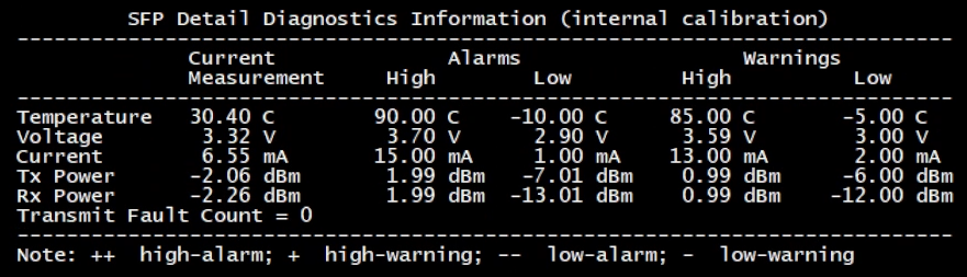
Figure 2: 10G DDM information
It is worth noting that, unlike 10G SFP+ transceivers, 100G optical modules usually consist of independent optical lanes.

Figure 3: 100G DDM information
In these modules, TX Power and RX Power appear per lane rather than as a single aggregated value. Under normal conditions, the optical power of all four lanes should remain within a similar range. If one lane shows significantly higher or lower TX or RX power, it may indicate an issue such as laser aging, internal coupling problems, or poor fiber connections.
For this reason, during testing and maintenance of 100G modules, engineers should not rely only on the overall link status. Checking TX Power and RX Power for each lane helps detect potential issues at an early stage.
Estimating Your Optical Power Budget
After understanding TX Power and RX Power, the optical link design must consider the optical power budget, which represents the maximum allowable link loss. This method also provides a practical way to estimate transmission distance.
Power Budget (dB) = TX Power (dBm) − RX Sensitivity (dBm)In simple terms:
Maximum transmitted optical power minus the minimum detectable received power equals the total allowable link loss.
If an SFP transceiver has a power budget of 20.9 dB, and standard single-mode fiber at a wavelength of 1550 nm has an attenuation of about 0.25 dB per kilometer, the estimated maximum transmission distance is 20.9 ÷ 0.25, or approximately 83 km.
This result represents a theoretical estimate. In real deployments, patch cords, connector losses, and ambient temperature also affect the actual received optical power.
For this reason, during deployment and testing, it is important to select SFP transceivers with transparent parameters and clearly defined specifications. In our current product portfolio, all models clearly list TX Power, RX Sensitivity, and acceptable RX Power ranges in the datasheet.

Figure 4: datasheet
What Factors Affect Optical Power?
Several factors influence TX and RX optical power, including:
- SFP transceiver specifications and operating conditions
- Fiber type and fiber length
- Fiber connection quality, including connector cleanliness and insertion loss
- Patch cords, distribution frames, and splice points along the link
- Operating environment temperature
Product datasheets list the normal TX and RX operating ranges for each model. These values help determine whether the optical power remains within a normal range. If the power falls outside this range, further investigation is required.
Common Optical Power Issues
# Optical Power Too Low:
High fiber attenuation, contaminated, poorly connected fiber interfaces, or aging optical components.
# Optical Power Overload:
Receiver overload may occur when long-reach transceivers operate over short distances or when direct connections lack optical links, leading to increased bit error rates.
In addition, incompatible optical modules may cause TX and RX power data to be displayed incorrectly on switches, whereas our products are designed to provide strong compatibility across different platforms.
Summary
TX Power and RX Power serve as core parameters for evaluating SFP transceivers and optical links. By understanding their meaning, measurement methods, and power budget calculations, you can complete link design and fault isolation more efficiently.
FAQs
Q: Does higher TX Power always mean a better link?
Not always. TX Power must remain within the designed range of both the transceiver and the link. Excessive power may cause Receiver overload.
Q: Is a negative RX Power value normal?
Yes. dBm is a relative unit. A negative value does not indicate a fault.