


Blog, Optical Transceiver
OSFP IHS vs. OSFP RHS: What Are the Differences and How to Choose?
May
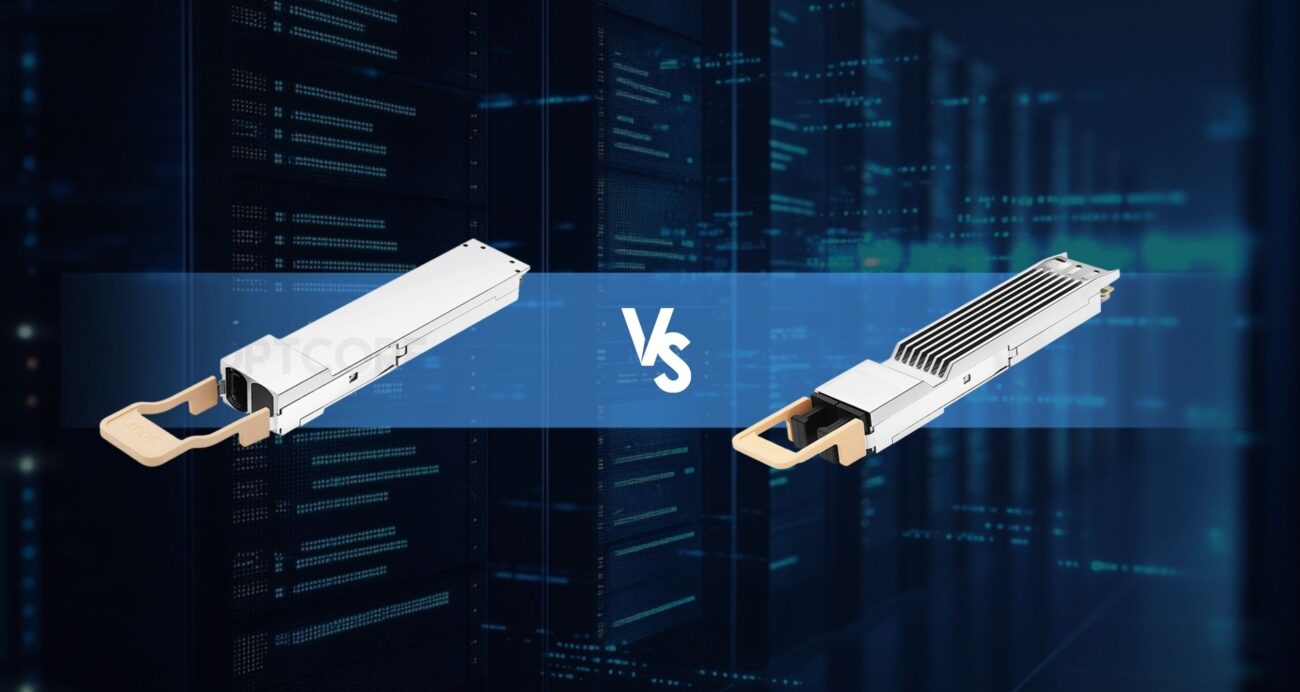
The 800G optical module industry is growing rapidly. As module speed increases, module power consumption also increases. The thermal density inside high-speed modules is much higher than before. Traditional cooling methods that rely on airflow switching are becoming insufficient for high-power modules. As a result, OSFP gradually developed two distinct thermal structures: IHS (Integrated Heat Sink) and RHS (Riding Heat Sink). They represent different optical module cooling methods, and different structures bring different results. So what are the actual differences between OSFP IHS vs. OSFP RHS, and what design factors should be considered when choosing between them? This article will explain these topics in detail.
Table of contents
What Is OSFP
OSFP (Octal Small Form-factor Pluggable) is a pluggable optical module form factor standard designed for 400G, 800G, and future 1.6T high-speed networks. Compared with QSFP-DD, OSFP allows taller module height, a larger top cooling area, and higher module power support. This is also one of the original design goals of OSFP.
OSFP is still essentially a high-speed SerDes interface module. After the high-speed switch ASIC outputs 112G PAM4 electrical signals, the signals enter the OSFP module through PCB traces. Then the DSP performs equalization, FEC coordination, clock recovery, and signal retiming, and finally drives the optical devices to complete optical-electrical conversion. In the 800G era, single-lane speed has already increased to 100G PAM4 or higher. DSP power consumption and heat generation are much higher than in the 56G era. Because of this, OSFP places more focus on thermal design than QSFP-DD.
AI networks have very high requirements for port bandwidth density and thermal capability, so OSFP has gradually become a mainstream package in many high-speed switches. OSFP can more easily support modules above 25W or even higher power levels. At the same time, the OSFP front-panel space is more suitable for future 1.6T module development, so more and more AI and HPC equipment are starting to prioritize OSFP structures.
OSFP IHS (Integrated Heat Sink)
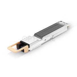
Integrated Heat Sink means the heat sink is integrated into the module itself. The main feature of this structure is that the heat sink directly belongs to the module body. The top of the module usually includes obvious metal fins or a large cooling structure, and uses front-to-back airflow to directly cool the module itself with air.
In terms of physical structure, IHS modules are usually taller than standard OSFP modules. The total height is generally between 13 and 21mm, and there is a complete aluminum or copper fin structure on the top to increase surface area and reduce thermal resistance. Since heat is mainly dissipated through the module itself first, IHS can support modules with higher TDP.
However, it is important to note that IHS does not always imply a finned top. IHS mainly has two structural variants.
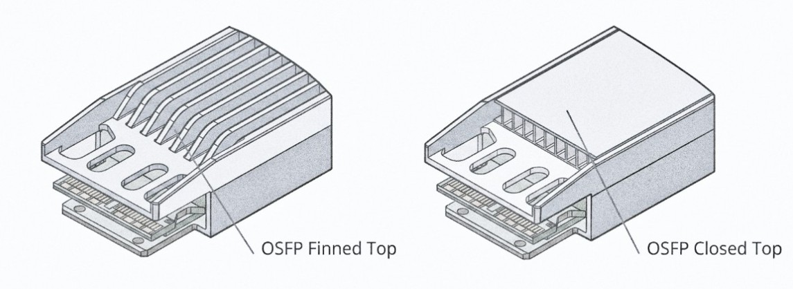
- Open-Top IHS: The fins are entirely open-air, and airflow flows directly into them, making it theoretically the strongest for air cooling. However, open-air fins make them vulnerable to impact, bending, and dust. Under conditions where the insertion and withdrawal actions happen regularly, its mechanical stability is weaker.
- Closed-Top IHS: An extra cover will be included on the outer part. It may have the same appearance as flat-top modules. Meanwhile, the cooling fins are still included within the modules. Such modules maintain their high performance in terms of thermal stability while improving their mechanical stability at the same time. Most of the 800G switches’ IHS modules are of the Closed-Top IHS design.
Therefore, whether fins appear visibly is not the sole criterion for determining whether a module is an IHS. What matters most is whether the heat sink is part of the module.
| Key Features | Limitations |
|---|---|
| Strong thermal performance | Taller module height |
| Uses switch airflow directly for cooling | Cannot fit low-profile PCIe NICs |
| Suitable for long-term high-load AI training | Higher module weight |
| Mature thermal ecosystem and compatibility | Higher mechanical stress during frequent insertion |
| Fits traditional air-cooled switch architecture | Requires stronger airflow design |
OSFP RHS (Riding Heat Sink)
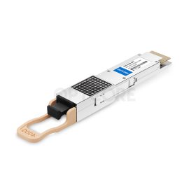
Compared to IHS, RHS does not allow the module to build a heat sink in its own package. Its principle lies in system-wide thermal management. Heat sinking is mainly accomplished through the switch/NIC system itself. The RHS modules maintain a flat-top appearance in general. There is no large cooling fin inside the module. Instead, the heat sink is actually on the equipment side.
After the module is installed, the cooling system will contact the module’s top surface through the Thermal Interface Material (TIM) and remove heat along with the system heat sink. Such a structure can lower the height of the module, thus enhancing port density on the panel. Meanwhile, since the heat sink is made by the switch system itself, the airflow control performance improves.
Since the module itself does not have a heat sink, RHS relies more on the vendor’s system’s thermal management. System air flow, pressure plate structure, TIM contacting efficiency, and cooling systems become critical factors affecting the stability of the module.
| Key Features | Limitations |
|---|---|
| Lower module height | Cannot dissipate heat independently |
| Better for NICs, DPUs, and liquid cooling systems | Relies on host thermal design |
| Helps increase front-panel density | Usually incompatible with IHS cages |
| Better for future high-density AI servers | Higher system-level design complexity |
| Easier to integrate into unified cooling systems | Stricter multi-vendor compatibility requirements |
OSFP IHS vs. OSFP RHS
| Item | OSFP IHS | OSFP RHS |
|---|---|---|
| Core Thermal Design | Module-integrated cooling | Host-managed cooling |
| Typical Height | 13–21mm | ~9.5mm |
| Top Structure | Finned-top / semi-enclosed | Flat-top |
| Main Cooling Method | Direct airflow cooling | TIM + host heatsink |
| Cage Type | Standard OSFP cage | OSFP-RHS cage |
| Typical Deployment | Switches | NICs / DPUs |
| Mechanical Space Requirement | Larger | Smaller |
| Weight | Higher | Lower |
Although IHS and RHS have obvious differences in thermal design methods, they are still part of the OSFP ecosystem. Both support high-speed PAM4 SerDes, electrical interface protocols, and 800G-class link capability. There is no difference at the protocol layer, and they do not affect the network operation itself.
However, it is important to note that the cage structures are not fully compatible. IHS and RHS usually correspond to different cage designs and cooling structures, so not all devices can mix them. When selecting modules, the first thing to confirm is the cage type supported by the equipment.
How to Choose For Your Situation
Choosing Based on Real Deployment Scenarios
If your deployment environment is a traditional air-cooled data center, and the equipment comes from multiple vendors, while flexible future module replacement is needed, then IHS is usually more suitable. Switches in this type of environment usually use standard OSFP cages and rely on front-to-back airflow for cooling. IHS modules have their own cooling structure, which reduces dependence on the internal thermal design of the switch.
If your network is part of AI training clusters or HPC environments, and the equipment power density is very high, RHS will become increasingly advantageous as liquid cooling or cold plate systems become more common in the future. Because the heat sink of the RHS is located on the system side, it is easier to combine with liquid cooling structures. Unified system-level thermal management is also very important.
When your equipment belongs to NIC or DPU scenarios, such as PCIe network cards, then RHS is usually the only option. This is because PCIe cards have strict height limits, while the heat sink height of IHS modules clearly exceeds standard NIC space. Therefore, in devices such as ConnectX-7 and ConnectX-8, RHS is basically a mandatory requirement. Similarly, when one switch deploys a large number of 800G ports, RHS modules with lower height make higher-density layouts easier to achieve. In comparison, IHS fins clearly occupy more vertical space.
Equipment Compatibility: What Works With What
In real deployment, various hardware components will have fixed thermal designs already.
AI switches will demand the use of IHS modules. This is the case with AI switch models like NVIDIA Spectrum-4, which includes SN5600, SN5600D, and SN5610. All these AI switches use a twin-port OSFP cage design and IHS modules. They cool the module’s top fin using strong airflow from the front to the back. The modules supported include 800G 2×SR4/SR8 and 800G 2×DR4/DR8 modules.
Compared with switches, NICs and DPUs usually can only use RHS structures. For example, ConnectX-7 OSFP NICs and the latest ConnectX-8 SuperNIC are the same. Although these devices already support 800G or higher bandwidth, RHS remains the only practical solution due to PCIe form-factor limitations when choosing OSFP IHS vs RHS.
-
Generic OSFP-800G-DR8 Compatible 800G 2xDR4/DR8 OSFP Finned Top 1310nm 500m Dual MPO-12/APC Transceiver
US$ 899.00 (Excl. VAT) -
Generic OSFP-800G-SR8 Compatible 800G 2xSR4/SR8 OSFP Finned Top 850nm 100m Dual MPO-12/APC Transceiver
US$ 599.00 (Excl. VAT) -
Generic QSFPDD-400G-SR8 Compatible 400GBASE-SR8 QSFP-DD 850nm 100m Transceiver
US$ 139.00 (Excl. VAT) -
Generic Compatible 400G DR4 QSFP-DD 1310nm 500m MTP/MPO-12 Transceiver
US$ 429.00 (Excl. VAT)
FAQs
#1 Is OSFP IHS always better for cooling?
Not necessarily. IHS can provide stronger module-level thermal performance, but the overall result still depends on equipment airflow design. Since RHS depends on system-level cooling, it can also achieve very good thermal performance in some situations.
#2 Can I use IHS modules in RHS systems?
Usually not. This is because the two structures correspond to different cage designs.
Conclusion
IHS and RHS are essentially two different thermal design routes. As 800G and AI switch power consumption continues to increase, these structural differences will become more important. Understanding their differences about OSFP IHS vs RHS, and making the correct choice is very important for the future management and development of network equipment.
Read more
- Flat Top vs. Finned Top OSFP: A Costly Mistake You Must Avoid in NVIDIA Networking
- SFP+, SFP28, QSFP+, QSFP28, QSFP56, QSFP-DD, QSFP112 vs OSFP, What are the differences?
- A Comprehensive Guide to 400G Ethernet DAC Cables