


Blog
How to Easily Clean Your 200G/400G/800G Transceivers in an AI Data Center
May
AI data centers are rapidly entering the 400G, 800G, and even 1.6T era. As GPU cluster sizes continue to grow, the number of high-speed optical transceivers is clearly increasing. Building a standardized cleaning and maintenance process for 200G/400G/800G transceivers has already become a very important part of modern AI data center operations and maintenance.
In high-speed network environments, small dust particles, IPA residue, human skin oil, or tiny scratches can create much larger impacts in 400G/800G environments. This finally causes link jitter and higher FEC correction pressure, affecting link stability. This article provides a detailed introduction to cleaning transceivers and their related connectors.
Table of contents
Why Fiber Cleaning Is Important in 200G/400G/800G Networks
First, let us know why learning how to clean 200G/400G/800G transceivers is important. Modern high-speed DSPs already support FEC correction capability, but FEC is not an unlimited recovery mechanism. After the bit errors caused by contamination exceed the DSP recovery threshold, the link enters an unstable state.
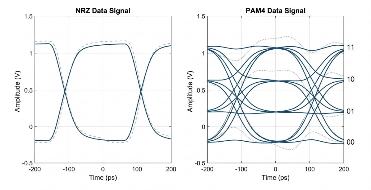
Traditional 10G NRZ only uses two levels to represent 0 and 1. As a result, the receiver side has a large decision margin. Even if the link has some insertion loss, small reflections, or a little noise, the receiver can still recover data correctly. But after the arrival of 100G and even 200G/400G/800G, PAM4 became the mainstream technology. Commonly used in QSFP56, QSFP-DD, and OSFP. PAM4 carries more bits in the same time by using four different levels, increasing single-lane speed. Although this improves bandwidth density, it also directly reduces the eye opening.
In 400G PAM4 links, the DSP must distinguish four amplitude states: 00, 01, 10, and 11. Compared with NRZ, the vertical PAM4 eye height is reduced by about one-third. This means the receiver becomes much more sensitive to noise, insertion loss, and reflection. Contamination that may only cause 0.2 dB insertion loss in a 10G link may directly cause a rapid Pre-FEC BER increase in a 400G link.
This is also why more and more data centers now require the standard “Inspect → Clean → Inspect” process. OPTCORE pays great attention to this point. Before packaging the sample, we carefully inspect the end faces and interfaces to keep transceivers clean before delivery and reduce contamination risks in high-speed links at the source.
-
Generic QSFP56-SR4-200G Compatible 200GBASE-SR4 QSFP56 850nm 100m Transceiver
US$ 289.00 (Excl. VAT) -
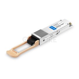
Generic Compatible 400G DR4 QSFP-DD 1310nm 500m MTP/MPO-12 Transceiver
US$ 429.00 (Excl. VAT) -
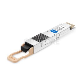
Generic QSFPDD-400G-SR8 Compatible 400GBASE-SR8 QSFP-DD 850nm 100m Transceiver
US$ 139.00 (Excl. VAT) -
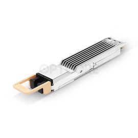
Generic OSFP-800G-SR8 Compatible 800G 2xSR4/SR8 OSFP Finned Top 850nm 100m Dual MPO-12/APC Transceiver
US$ 599.00 (Excl. VAT)
Common Fiber Cleaning Methods
Dry Cleaning
Dry cleaning is mainly used for light dust, static particles, and routine maintenance scenarios. These methods usually do not produce liquid residue, so they are also the most commonly used in data centers. Common tools include LC/SC click cleaners, MPO cleaners, and lint-free optical wipes. LC interfaces usually use 1.25mm cleaners. MPO/MTP interfaces must use dedicated MPO cleaners to cover the guide pin area.
Wet Cleaning
Wet cleaning is mainly used for oil contamination, static adsorption contamination, residue films, and heavily contaminated interfaces. It usually uses high-purity 99% IPA or engineered fast-evaporating optical solvents. Compared with traditional IPA, these solvents evaporate faster and leave less residue, making them more suitable for PAM4 environments. Wet cleaning is usually used together with lint-free optical wipes, fiber cleaning sticks, or foam swabs.
Internal Interface and Special Interface Cleaning
200G/400G/800G transceivers often have exposed lenses, MPO connectors, and internal optical windows. Cleaning these surfaces requires the use of specialized tools such as dust-free optical foam swabs and cleaning rods, and an inspection microscope with 200x to 400x magnification is recommended to verify that the fiber end-face is clean. Regular cotton swabs or common fibers are not suitable for this task.
How to Clean 200G/400G/800G Transceiver
Preparation Before Cleaning: Inspection
Before starting the cleaning process, please inspect the end-face of 200G/400G/800G transceivers. This is the most important first step. Blind cleaning should be avoided. Common inspection devices include digital fiber inspection scopes. These devices can magnify LC and MPO end-faces and identify different contamination conditions. They can distinguish floating dust, fingerprint oil contamination, IPA residue films, micro-scratches, and guide pin contamination areas.
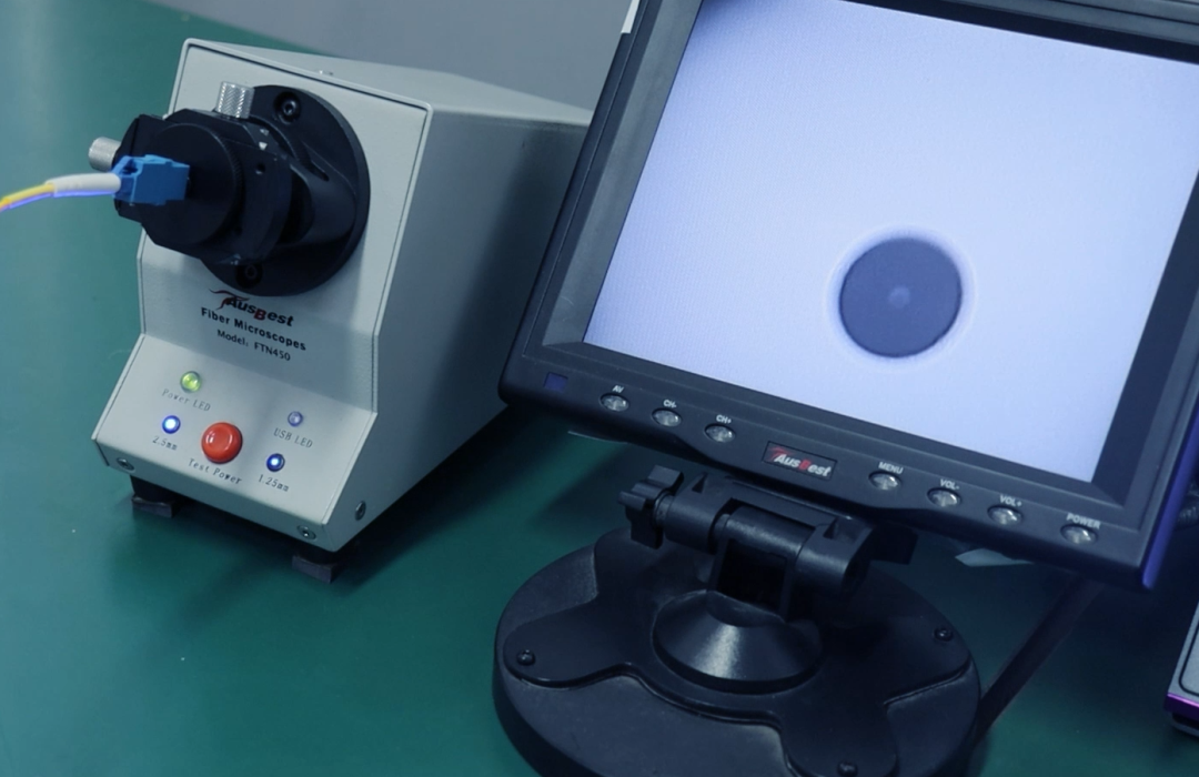
For example, floating dust usually appears as random particles, while human skin oil forms spread film layers. Scratches usually appear as reflective linear marks. Different adapters are required for different interface types. For MPO interfaces, the guide pin area also requires special inspection to prevent hidden contamination within the guide holes.
After inspection, the appropriate tools should be prepared based on the interface type. At the same time, the working environment is also important. Cleaning should be avoided in dusty or high-airflow environments, and the work surface should remain clean.
One easily ignored issue is that many engineers assume brand-new patch cords are always clean. In reality, plastic friction inside dust caps during transportation produces many micro-particles. Many 400G links exhibit BER issues during the first deployment because contamination is already present in the new cable. Therefore, even new patch cords should still be inspected before connecting to production networks.
Cleaning with Fiber Optic Cleaners
However, if there is only ordinary dust or even just static, dry click cleaners will do. When dealing with LC connectors, mechanical cleaners in sizes like 1.25mm are preferable. In addition, for 400G FR4 and LR4 single-mode, lower-particle cleaners are preferred, as PAM4 systems are much more sensitive than other systems.
Here’s how to clean 200G/400G/800G transceivers with click cleaners. When working with such connectors, first make sure that the interface does not move. Do not allow the LC ferrule to tilt. Insert the mechanical cleaner into the interface vertically and push down once. When cleaning a patch cable, remove the smaller cap of the cleaner and put the patch cable into the connector. To clean the internal parts of the transceiver, remove the larger cap from the cleaner and insert it into the transceiver connector.
Regarding MPO connectors, specialized MPO cleaning devices must be used. First, check for any particles around the guide pins, then clean the connector in a single direction. During the process, it is important to keep the cleaner completely horizontal. When MPO connector cleaning is done, the connection needs to be made immediately, or the dust caps need to be put back on.
-
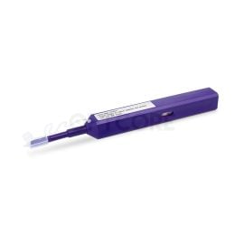
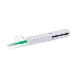
FOC-125 One-Click Fiber Optic Cleaner Pen for 1.25mm LC/MU Connectors (800 cleans)
Original price was: US$ 14.00.US$ 9.90Current price is: US$ 9.90. (Excl. VAT) -
One-Click Fiber Optic Cleaner Pen for 2.5mm SC/FC/ST Connectors (800 cleans)
Original price was: US$ 14.00.US$ 9.90Current price is: US$ 9.90. (Excl. VAT) -
One-Click Fiber Optic Cleaner Pen for MPO/MTP Connectors (600 cleans)
Original price was: US$ 35.00.US$ 26.00Current price is: US$ 26.00. (Excl. VAT) -
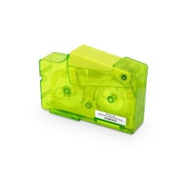
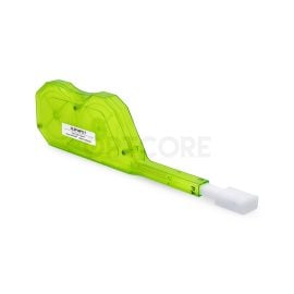
FOC-KCC-550 Fiber Optic Cleaning Cassette for LC/SC/FC/ST/MU/D4/DIN MTP/MPO Connectors
US$ 16.00 (Excl. VAT)
Cleaning with Wipes and Solvents
Examples of materials used include class 10 optical wipes, optical foam swabs, and engineered fast-evaporation solvents. Unlike conventional 99% IPA, these engineered solvents have faster evaporation rates and less residue, making them more appropriate for the 112G PAM4 environment.
Here’s how to clean 200G/400G/800G transceivers with wipes and solvents. Add a very small amount of solvent to the front part of the lint-free wipe so that only a slightly wet area forms. Then press the LC ferrule lightly onto the wet area and slowly drag it in one direction toward the dry area. This action should not move back and forth, nor should it stop midway. The solvent dissolves the oil contamination, and the dry area immediately absorbs it. After cleaning, wait several seconds for complete evaporation.
The amount of solvent should be carefully controlled, especially at MPO interfaces, where guide pin areas readily trap liquid. Excess solvent may remain inside the guide pin holes. In addition, avoid using “figure-eight” cleaning motions. Many old network environments used this method for SC/ST interfaces, but LC ferrules are much smaller. Figure-eight motions can easily roll the connector and bring oil contamination from the plastic housing back onto the glass center area.
Internal interfaces inside OSFP and QSFP-DD transceivers usually do not use normal wipes directly. Instead, low-particle foam swabs are used for local cleaning.
Re-Inspection
Cleaned transceivers and patch cords should be reinserted into the inspection scope for reinspection. This ensures that the cleaned module and end face are free of contamination. Only then is the cleaning process considered complete.
For the complete workflow, related reference videos are also available.
Preventing Transceiver Contamination
- Build a Standard “Inspect → Clean → Inspect” Process: Transceiver maintenance should be part of standard operating procedures. Before connecting to production equipment, all modules should first be checked using a digital inspection scope. After cleaning, contamination must be rechecked to confirm it has been removed.
- Avoid Long-Term Exposure and Incorrect Storage: During use, all unused interfaces should be immediately covered with dust caps, and patch cords should not remain hanging or exposed. For long-term-stored modules, dust caps should also be checked regularly.
- Reduce Unnecessary Plugging and Incorrect Operations: Frequent plugging and unplugging should be minimized, as repeated operations increase the accumulation of scratches. In addition, LC/MPO end-faces and internal optical areas should never be touched directly by hand. Anti-static gloves should be worn during operation to prevent both ESD damage and the transfer of contaminants from fingerprints.
Conclusion
Learning how to clean 200G/400G/800G transceivers is a very important part of network maintenance. In many cases, it directly affects link stability and transceiver lifetime. Cleaning 200G/400G/800G transceivers is not complicated and does not require a major investment, but it may greatly affect your links and extend service life. Because of this, maintaining proper cleaning procedures is very important.
Read more
- How to Protect Fiber Optic Cables – A Beginner’s Guide
- What Is Optical Return Loss: A Beginner’s Guide
- MPO-8, MPO-12, or MPO-24? Choosing the Right Backbone for Your 400G Infrastructure
- 400G SR4 vs DR4 vs FR4 vs LR4: What Are the Differences and How to Choose?