Technology changes the life, informatization is the trend of the development of the world today. Networking, cloud computing, large data and other emerging network information technology innovation and application, and in mobile interconnection technology, the 3G network is maturing, 4G LTE network from the beginning of last year in the national pilot run, mobile interconnection speed will be a new step. In this era of information industrialization, we work and live in the city is also in the transformation of the Intelligent city, a variety of network applications are closely related to us. Whether it is the application of new technology or the construction of the Intelligent city, the application cannot be separated from the basic network. The construction of the basic network is based on the site, the active terminals, and interconnecting devices, as well as the basic interconnection channel-cabling system. Cabling system needs to be installed on the site, easy to be affected by environment, product quality, installation process and other factors, is the most important link to determine the quality of network transmission. The reliability of Cabling system depends not only on the quality supervision in the project but also on the final field acceptance test.
The urgency of test technology development
At present, most of the small and medium-sized cabling projects still use 10 Gigabit as the backbone to achieving Gigabit to the desktop network architecture. However, with the rapid development of 3G / 4G and Internet services, bandwidth cannot meet the needs of applications. The main link uses 40G / 100G to become a large-scale wiring project, especially the inevitable trend of enterprise data center and Internet IDC data center project construction. According to IDC market report, after 2015, 40G / 100G will gradually become the mainstream port rate.
Since the IEEE released the 802.3ba 40G / 100G standard in June 2010, the 40G / 100G network has mainly been based on experimental networks and has fewer requirements for on-site testing. After more than two years of systematic research and development testing, the current 40G / 100G transmission technology is maturing, major manufacturers have introduced 40G / 100G switching routing equipment, carrier-class long-distance backbone link using single-mode optical fiber systems, and buildings and data centers The integrated cabling system is mainly based on multimode OM3 / OM4 optical fiber system transmitting over short distances. It adopts 12-pin MPO connector and four-channel / ten-channel pre-connected optical cable. Pre-connected optical cable greatly reduces installation time and labor costs, but how to quickly identify the polarity of the fiber, fast and accurate test of the link attenuation has become the primary problem of field testing.
Traditional optical fiber testing technology
First of all, let us first review the original Gigabit, 10 Gigabit optical fiber link test technology. In 2003, TIA-526-14-A multi-mode optical cable installation light intensity loss test standard formally defines the CPR (CoupledPowerRatio) optical coupling rate detection method, the light source is divided into five levels (as shown below), LED light source is level 1 Light source, VCSEL The vertical cavity surface emits a laser light source at a level between level 3 and level 4, and the FP laser light source corresponds to a level 5 light source. At the same time, the test limits of optical loss are further increased. The maximum loss value of 1000BASE-SX applied to OM1 optical fiber is 2.6dB. The maximum loss value of 10GBASE-SR applied to optical fiber OM3 is 2.6dB. This standard, as a common standard for optical fiber link testing, is not aimed at specific network applications. It emphasizes the normal state of optical signal transmission. It is recommended to use LED light sources to test multimode fiber links. This method can detect the worst fiber link Happening. The laser-optimized VCSEL light source is used to detect the link for a specific network application. For example, if the active device uses a VCSEL light source or the current network is to be upgraded to use a VCSEL light source, the measured fiber loss value is relatively close to the real loss in the network application value.
The TIA-526-14-A standard is referenced by several related test standards such as ANSI / TIA / EIA-568-B, ISO / IEC11801, ISO / IEC14763-3 and others. And ANSI / TIA / EIA568-B.1.7.1 and ISO / IEC14763-36.22 also specify the size and use of 50 / 62.5um multimode fiber spools. The reel is modeled as a mode filter by means of a coiled optical fiber to reduce the high mode generated by the light source in the optical cable and reduce the difference of test results caused by different light sources and improve the stability and repeatability of multimode optical fiber testing.
10G MPO multi-core fiber test solution
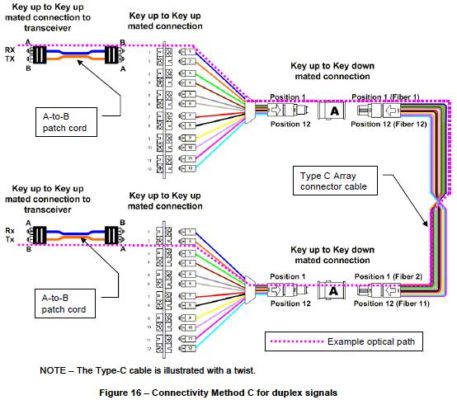
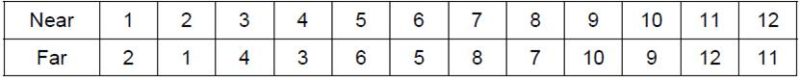
Compared with traditional dual-core fiber optic connectors such as LC, SC, and ST, MPO connectors can support at least 12-core optical fibers. The MPO connector is mainly used for pre-attached optical fiber cables. Because MPO optic fiber has 12 core channels, TIA-568-C.0-2009B.4 has analyzed the channel polarity in detail, for the duplex transmission, there are mainly three kinds of polarities A, B, C connections. All three methods are for a common goal —- to create an end to end optical transceiver channel, but the three ways cannot be compatible, respectively, using different polarity connectors and adapters. For the entire link compatibility and consistency, as far as possible to consider the use of the same polarity connectors and adapters, such as the use of the jumper polarity are AB, adapter types are KEYUP-KEYUP, or the polarity will cause different Confusion, easy to install error, resulting in link failure. Therefore, in the 10G Fiber Channel, the MPO main link polarity mainly adopts Class C (see below). The two ports are internally interoperable according to the corresponding numbers. The optical channels are connected in groups of two or more, such as 1- – 2, 2 — 1, forming a full-duplex transceiver channel. The left and right ends are converted into the LC interface through the MPO to LC module box and then connected to the device through the LC jumper. This situation is mainly used in the data center high-density cabling system.
Measured link:
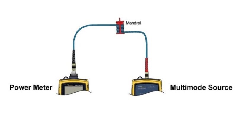
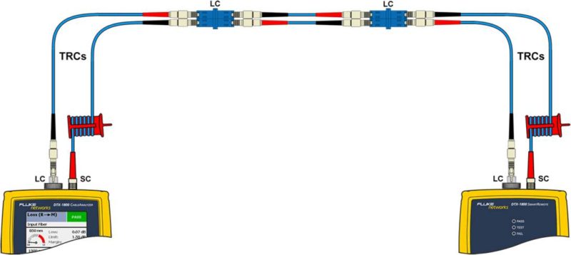
(1) Set the reference: connect the tester’s light source output (LC) and power meter input (LC) with one LC-LC test jumper.
(2) Unplug fiber jumper in the optical power meter input port, connect another fiber jumper.
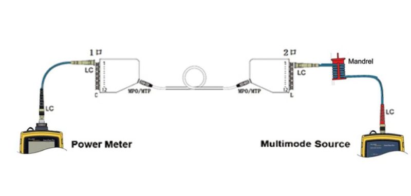
(3) Connect to the measured optical fiber (both ends of the MTP-LC module box, the middle is MTP-MTP pre-connected optical cable), the LC Test jumper respectively connect to both ends of a module, one end of 1, the other end of 2 ports.
(4) Record the loss of the current measured fiber channel, then replace the light source LC jumper to a Module 2, the Optical power meter end LC jumper to the other side of a module of 1, record and save until the completion of 12 channels of loss testing.
In 2010, the 40G / 100G link standards promulgated by 802.3ba were 40GBASE-SR4 and 100GBASE-SR10 respectively; the connectors and adapters using MPO were used; the maximum transmission distance of OM3 optical fiber was 100 meters and the maximum loss value was 1.9dB; OM4 The maximum optical fiber transmission distance of 150 meters, the maximum loss of 1.5dB. The 40G / 100G links are mainly used for data traffic transmission in the data center. According to the third-party statistics, 88% of backbone links in a data center does not exceed 100 meters in length. Therefore, the MPO pre-attached optical cable based on OM3 / OM4 will be the first choice for 40G / 100G links. The thresholds previously defined for 10G fiber link testing, such as the LC connector threshold of 0.75dB, allows for multiple connectors (more than two), and the threshold of 0.3dB for the splice point no longer applies. The new 40G / 100G fiber backbone links will use pre-attached fiber optic cables with no splice points and connectors in the link, simply by considering the loss of MPO connectors at both ends and the loss of the fiber optic cable itself, minimizing connector loss, Make sure the attenuation of the entire link is within the new standard.
The two key factors that affect 40G / 100G transmission are the light source and fiber link loss. More stringent loss requirements challenge the traditional LED light source testing method. The original LED light source has low output power, large divergence angle, large connector loss, and OFL-Overfilled injection. However, with the UFL-Underfilled Launch method, the near-field intensity light channels are concentrated in the center, and the transmission modes in the fiber center are few and the divergence angles are small, which effectively solves the disadvantages of the LED light source. However, the original standards such as IEEE802.3, ANSI / TIA and ISO / IEC are only defined for LED light sources, taking into account the price factor and the wide variations in the optical power distribution of VCSELs from different manufacturers. Therefore, the test for 40G / 100G The new standard is not defined using a VCSEL light source. Similarly, the ISO / IEC 14763-3 issued in 2006 defines the modal power distribution (MPD) method. Although the coupling strength is improved by the waveguide array, the same cannot meet the requirement of 40G / 100G transmission.
October 2010, ANSI / TIA-526-14-B replaces ANSI / TIA-526-14-A and defines a test method for the annular flux of an EF (Encircled Flux) light source, which is also defined in IEC 61280-4-1 Standard. EF limits the emission conditions of the multimode light source through mode regulators, filters the high-order optical signals, and replaces the common test jumpers using multi-mode spools with jumpers on a substitute EF controller (see below). Use 1 or 3 test jumpers when the connector under test and the test equipment connector are the same. Use 3 test jumpers when the connector under test and the test equipment are different. Test the jumper at least 2 Meters, no more than 10 meters. The loop flux reduces the measurement error in loss measurement from ± 40% to ± 10%, reducing measurement uncertainty and increasing repeatability for each measurement.
40G / 100G MPO fiber test method
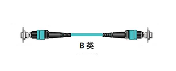
A standard MPO / MTP link consists of two MPO jumpers on each end, two MPO adapters, and a pre-attached backbone cable for the MPO. In TIA-568-C.0-2009B.4, for parallel multi-channel transmission, A and B are given two ways (see below, Table5).
In order to ensure the compatibility and uniqueness of the link, construction and maintenance is more convenient, especially the frequent Plug and replace MPO jumper, in the 40G / 100G cabling system, type B will be more adopted. The number of channels for 40G and 100G is different, but the transmission link model is the same, using the MPO/MTP interface for end-to-end transmission. Therefore, we take 40G single channel transmission as an example, the test should pay attention to the pre-attached cable and jumper port Port type—there is a guide pin (male) and no guide pin (female)
MPO Link (female-female):
Traditional MPO Multi-core fiber testing method—light source and optical power meter with LC interface
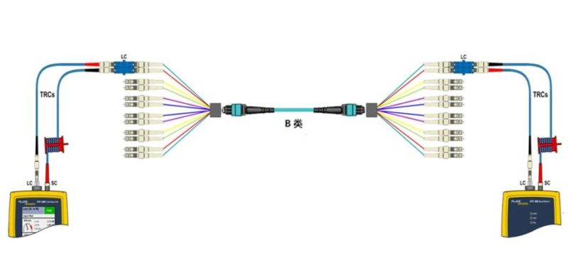
(1) Set benchmark: Using the 3-segment fiber jumper and 2 LC adapters for benchmarking, the light source exports the export side using a multimode reel, as shown in the following figure.
(2) Remove the intermediate LC short jumper between two LC adapter, add 2 LC-MPO (male) of the multi-core jumper, connect to the 1st LC, for testing MPO 1st, 2, as shown in the following figure.
(3) Measure MPO fiber link access, test, the MPO 1st, 2 attenuation value and save.
MPO Link (female-female):
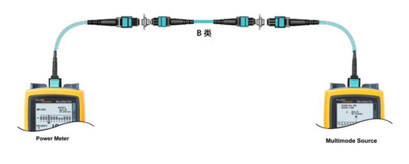
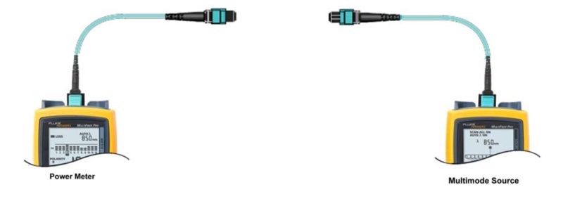
(1) Set benchmark: Use 1 MPO (male-male) test jumper connection light source and optical power meter.
(2) Disconnect the optical power meter end jumper, and then connect an MPO (male-male) test jumper
(3) Tested B-type fiber link access, to test the fiber polarity and 12 channels of loss, to save the test results.
(4) Repeat steps 2) through 3 to test the next MPO (female-female) fiber optic link.
Conclusion
The original 10G MPO test method is no longer suitable for the future 40G / 100G test needs, LC interface, light source, and optical power meter MPO fiber optic link led to a significant increase in the number of test times and time, a 12-core MPO trunk link complete test needs nearly ten Minute, and test stability is poor. Therefore, the test instrument with MPO interface needs to be tested. At the same time, EF loop flux control replaces multi-mode spooling, increasing the stability and reliability of fiber link testing. 100G transmission using the ten-channel receive and ten-channel mode is more complicated, IEEEP802.3bm40G / 100G working group will be 100G transmission mode to improve the original ten-channel transceiver mode will be replaced by the four-channel. As the next generation of 40G / 100G, up to 400G Ethernet transmission standard is about to start next year, is expected to use OM4 fiber. MPO interface optical fiber link deployment in the future will be more and more widened, no longer limited to high-end users such as telecom operators and data centers, understand the MPO optical fiber link transmission model and testing technology will help us better Control the future of 40G / 100G high-speed communications transmission channel.


 (2) Unplug fiber jumper in the optical power meter input port, connect another fiber jumper.
(3) Connect to the measured optical fiber (both ends of the MTP-LC module box, the middle is MTP-MTP pre-connected optical cable), the LC Test jumper respectively connect to both ends of a module, one end of 1, the other end of 2 ports.
(2) Unplug fiber jumper in the optical power meter input port, connect another fiber jumper.
(3) Connect to the measured optical fiber (both ends of the MTP-LC module box, the middle is MTP-MTP pre-connected optical cable), the LC Test jumper respectively connect to both ends of a module, one end of 1, the other end of 2 ports.
 In 2010, the 40G / 100G link standards promulgated by 802.3ba were 40GBASE-SR4 and 100GBASE-SR10 respectively; the connectors and adapters using MPO were used; the maximum transmission distance of OM3 optical fiber was 100 meters and the maximum loss value was 1.9dB; OM4 The maximum optical fiber transmission distance of 150 meters, the maximum loss of 1.5dB. The 40G / 100G links are mainly used for data traffic transmission in the data center. According to the third-party statistics, 88% of backbone links in a data center does not exceed 100 meters in length. Therefore, the MPO pre-attached optical cable based on OM3 / OM4 will be the first choice for 40G / 100G links. The thresholds previously defined for 10G fiber link testing, such as the LC connector threshold of 0.75dB, allows for multiple connectors (more than two), and the threshold of 0.3dB for the splice point no longer applies. The new 40G / 100G fiber backbone links will use pre-attached fiber optic cables with no splice points and connectors in the link, simply by considering the loss of MPO connectors at both ends and the loss of the fiber optic cable itself, minimizing connector loss, Make sure the attenuation of the entire link is within the new standard.
The two key factors that affect 40G / 100G transmission are the light source and fiber link loss. More stringent loss requirements challenge the traditional LED light source testing method. The original LED light source has low output power, large divergence angle, large connector loss, and OFL-Overfilled injection. However, with the UFL-Underfilled Launch method, the near-field intensity light channels are concentrated in the center, and the transmission modes in the fiber center are few and the divergence angles are small, which effectively solves the disadvantages of the LED light source. However, the original standards such as IEEE802.3, ANSI / TIA and ISO / IEC are only defined for LED light sources, taking into account the price factor and the wide variations in the optical power distribution of VCSELs from different manufacturers. Therefore, the test for 40G / 100G The new standard is not defined using a VCSEL light source. Similarly, the ISO / IEC 14763-3 issued in 2006 defines the modal power distribution (MPD) method. Although the coupling strength is improved by the waveguide array, the same cannot meet the requirement of 40G / 100G transmission.
October 2010, ANSI / TIA-526-14-B replaces ANSI / TIA-526-14-A and defines a test method for the annular flux of an EF (Encircled Flux) light source, which is also defined in IEC 61280-4-1 Standard. EF limits the emission conditions of the multimode light source through mode regulators, filters the high-order optical signals, and replaces the common test jumpers using multi-mode spools with jumpers on a substitute EF controller (see below). Use 1 or 3 test jumpers when the connector under test and the test equipment connector are the same. Use 3 test jumpers when the connector under test and the test equipment are different. Test the jumper at least 2 Meters, no more than 10 meters. The loop flux reduces the measurement error in loss measurement from ± 40% to ± 10%, reducing measurement uncertainty and increasing repeatability for each measurement.
In 2010, the 40G / 100G link standards promulgated by 802.3ba were 40GBASE-SR4 and 100GBASE-SR10 respectively; the connectors and adapters using MPO were used; the maximum transmission distance of OM3 optical fiber was 100 meters and the maximum loss value was 1.9dB; OM4 The maximum optical fiber transmission distance of 150 meters, the maximum loss of 1.5dB. The 40G / 100G links are mainly used for data traffic transmission in the data center. According to the third-party statistics, 88% of backbone links in a data center does not exceed 100 meters in length. Therefore, the MPO pre-attached optical cable based on OM3 / OM4 will be the first choice for 40G / 100G links. The thresholds previously defined for 10G fiber link testing, such as the LC connector threshold of 0.75dB, allows for multiple connectors (more than two), and the threshold of 0.3dB for the splice point no longer applies. The new 40G / 100G fiber backbone links will use pre-attached fiber optic cables with no splice points and connectors in the link, simply by considering the loss of MPO connectors at both ends and the loss of the fiber optic cable itself, minimizing connector loss, Make sure the attenuation of the entire link is within the new standard.
The two key factors that affect 40G / 100G transmission are the light source and fiber link loss. More stringent loss requirements challenge the traditional LED light source testing method. The original LED light source has low output power, large divergence angle, large connector loss, and OFL-Overfilled injection. However, with the UFL-Underfilled Launch method, the near-field intensity light channels are concentrated in the center, and the transmission modes in the fiber center are few and the divergence angles are small, which effectively solves the disadvantages of the LED light source. However, the original standards such as IEEE802.3, ANSI / TIA and ISO / IEC are only defined for LED light sources, taking into account the price factor and the wide variations in the optical power distribution of VCSELs from different manufacturers. Therefore, the test for 40G / 100G The new standard is not defined using a VCSEL light source. Similarly, the ISO / IEC 14763-3 issued in 2006 defines the modal power distribution (MPD) method. Although the coupling strength is improved by the waveguide array, the same cannot meet the requirement of 40G / 100G transmission.
October 2010, ANSI / TIA-526-14-B replaces ANSI / TIA-526-14-A and defines a test method for the annular flux of an EF (Encircled Flux) light source, which is also defined in IEC 61280-4-1 Standard. EF limits the emission conditions of the multimode light source through mode regulators, filters the high-order optical signals, and replaces the common test jumpers using multi-mode spools with jumpers on a substitute EF controller (see below). Use 1 or 3 test jumpers when the connector under test and the test equipment connector are the same. Use 3 test jumpers when the connector under test and the test equipment are different. Test the jumper at least 2 Meters, no more than 10 meters. The loop flux reduces the measurement error in loss measurement from ± 40% to ± 10%, reducing measurement uncertainty and increasing repeatability for each measurement.


 (2) Disconnect the optical power meter end jumper, and then connect an MPO (male-male) test jumper
 (3) Tested B-type fiber link access, to test the fiber polarity and 12 channels of loss, to save the test results.