


Blog, Optical Networking
FBT Splitter vs. PLC Splitter Comparison: What is the difference? (2026)
May
In 2026, as fiber-optic communication continues to evolve, the selection of optical splitters as fundamental components in passive optical networks directly affects overall link performance and long-term reliability. Accurately understanding the principles, differences, and applicable boundaries of the FBT vs. PLC splitter, two mainstream solutions, is a fundamental skill that network designers must master. This article provides a clear technical comparison of the definitions, technical principles, key performance differences, and selection conclusions.
Table of contents
What is an FBT splitter?
The FBT (Fused Biconic Taper) splitter is a splitter device manufactured using traditional optical coupling technology. Its manufacturing process is very intuitive: two or more stripped, coated optical fibers are bundled side by side in a specific configuration and uniformly stretched in opposite directions in a high-temperature molten state, forming a double-cone-coupled waveguide structure in the tapered region.
During the stretching process, technicians control the splitting ratio by monitoring the output optical power of each channel in real time. After reaching the target value, the cone is terminated, fixed to the quartz substrate with epoxy resin, and finally sealed in a stainless steel tube.
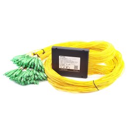
This process determines several basic characteristics of FBT splitters. Firstly, a single taper can achieve a maximum of 1 × 4 splitting, and for 1 × 8 or higher port counts, multiple 1 × 2 units can only be cascaded via fiber fusion splicing. For example, a 1 × 8 device contains seven 1 × 2 basic units inside. Secondly, the splitting ratio can be customized by twisting the optical fiber or stretching it to unequal lengths.
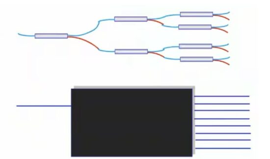
Figure 1: 1:8 FBT splitter
It can be used to make uniform 50:50 splitters, as well as non-uniform splitters of 5:95, 30:70, or even 1:99, which is the most unique capability of FBT. Thirdly, because the coupling region is optimized for specific wavelengths, FBT splitters operate only in three wavelength windows at 850 nm, 1310 nm, and 1550 nm and cannot cover other bands. These characteristics enable FBT splitters to maintain an irreplaceable position in low port count and non-uniform splitting-dependent scenarios.
What is a PLC splitter?
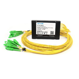
A PLC (Planar Lightwave Circuit) splitter is an integrated optical splitter device made using semiconductor wafer technology. Its core is a quartz or special glass chip that forms a Y-shaped optical waveguide array within the chip using planar processes such as photolithography, etching, and development. The chip’s input and output terminals are precisely aligned, coupled to multi-channel fiber arrays (FA), and then packaged as a whole in a microbox that meets Telcordia standards.
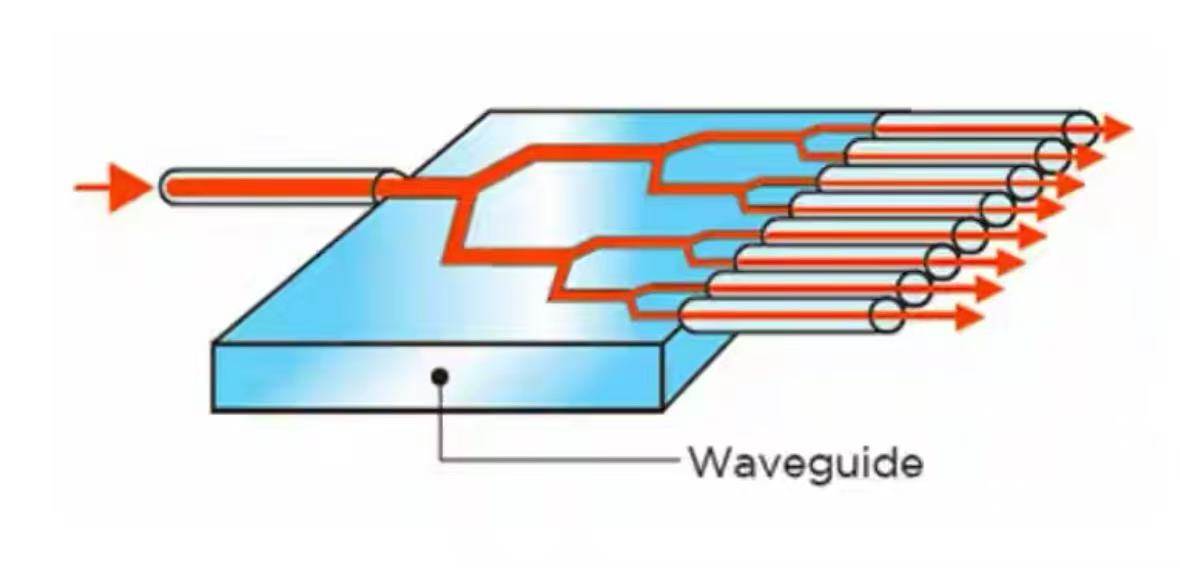
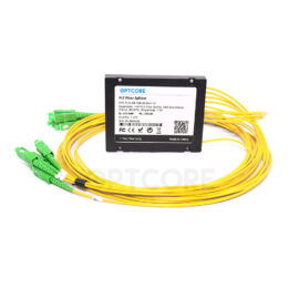
Figure 2: PLC splitter
The working mechanism of the PLC splitter determines its performance, which is completely different from that of FBT. The waveguide branches on the chip are designed with precise geometries, and each Y-branch achieves a strict 3dB power split. After multi-level branching, the optical power of all output ports is highly consistent.
The waveguide material and structure ensure stable operation over the full wavelength range of 1260 nm to 1650 nm, and a single chip can achieve a splitting ratio of 1 × 64 or even 1 × 128 without cascading. In addition, the chip uses a batch manufacturing process similar to that of integrated circuits.
Six-inch wafers can process hundreds of devices at once, with a single chip yield rate of over 95%. The performance repeatability between products is excellent and unaffected by fluctuations in the consistency of manual cone drawing.
FBT vs. PLC splitter: the differences between them
The performance differences between FBT and PLC are reflected in many dimensions. The table below compares the core parameters and then conducts a deep analysis of the key differences.
| FBT splitter | PLC splitter | |
| operating wavelength | Only 1310/490/1550nm and other single-port | 1260-1650nm full waveband |
| Maximum spectral ratio | Usually ≤1:32; need cascade | A single chip of 1:64; some can reach 1:128 |
| Uniformity between ports | Over 1×8 has big differences and can reach several dBs | End-to-End ≤ 0.8 dB |
| Insertion loss | The low port is nearly the same; the high port increases due to cascading | Low and the same in total |
| Working temperature | -5°C to +75°C | -40°C to +85°C |
| Polarization loss | Accumulation after cascading can reach over 0.3 dB | Normally <0.2 dB |
| Device size | After adding ports, it will become bigger | Compact and small |
| Long-term reliability | Multiple cascaded fusion points: failure rate rises with ports | Chip-level integration, really low failure rate |
In terms of wavelength coverage, the full band capability of PLC means that it can simultaneously carry GPON’s 1310 nm upstream, 1490 nm downstream, and 1550 nm video overlay, as well as the newly added wavelengths of XGS-PON or 25G-PON in the future, perfectly adapting to the triple network fusion network of multi-wavelength co-transmission.
FBT is limited by its three-window operation, and once a network upgrade introduces a new wavelength, there may be abnormal port power or even chain failure. This has been repeatedly verified in current network cases: when the operator upgrades the original EPON network to 10G-EPON, some of the splitter links that introduce L-band wavelengths exhibit significant excess losses in FBT devices, while PLC links are completely unaffected.
The difference between spectral uniformity and insertion loss is sharply amplified at high spectral ratios. The optical signal from each output port of the PLC splitter passes through the same series of Y branches, with the same path length and bending loss height.
In a 1 × 32 configuration, the power difference between ports does not exceed 0.8 dB. The FBT splitter is different, as each 1 × 2 unit in the cascade will exhibit a slight deviation in the splitting ratio, and the cumulative power difference between ports after a multi-stage series connection can reach several dB.
Reflected on the user side, the difference in received optical power between adjacent ONUs may be 2-3dB, which directly leads to video lag and fluctuations in internet speed for some users. However, the total attenuation of the splitter seen by the upper-layer network management does not provide any warning, making troubleshooting extremely difficult.
Temperature stability and long-term reliability are another decisive boundary. PLC devices can operate stably in a wide temperature range of -40°C to +85°C, with temperature-induced losses as low as 0.2 dB.
FBT splitters can operate from -5°C to +75°C, making them not that suitable for uncontrolled-temperature environments and remote base stations.
Microcracks can develop in optical splitters due to environmental thermal stresses, which may not be detected during initial testing and can eventually lead to performance issues such as power attenuation after these devices are deployed outdoors. The problem was only fully resolved after the system was replaced with PLC splitters.
The unique capability of non-uniform spectroscopy is an advantage that FBT technology rarely offers. Traditional PLC splitters do not currently support arbitrary, non-uniform splitting ratios required for precise fiber-optic line monitoring or specialized signal extraction.
In terms of cost and availability, FBT splitters with low port numbers (1 × 4 and below) maintain a little price advantage with simple raw materials and high equipment efficiency; PLC splitters with a size of 1 × 8 and above, due to the lack of multi-level cascading and mass production, have lower unit port costs than FBT products of the same level. The 1×8 PLC splitter evenly distributes optical signals from one input fiber to eight output fibers, making it a common component in network cost and performance planning.
Recommended products
-
1×64 PLC Fiber Splitter, ABS Box Module, 2.0mm, SC/APC, Singlemode
US$ 69.00 (Excl. VAT) -
1×128 PLC Fiber Splitter, ABS Box Module, 2.0mm, SC/APC, Singlemode
US$ 369.00 (Excl. VAT) -
1×16 PLC Fiber Splitter, ABS Box Module, 2.0mm, SC/APC, Singlemode
US$ 21.00 (Excl. VAT) -
1×8 PLC Fiber Splitter, ABS Box Module, 2.0mm, SC/APC, Singlemode
US$ 14.00 (Excl. VAT)
Conclusion
Looking ahead to 2026 and beyond, the widespread adoption of 10G PON, the initial integration of 25G/50G PON in experimental networks, and the continued expansion of wavelength division multiplexing are expected to shape the evolution of passive optical networks. In the access layer, the requirements for wavelength expansion and port uniformity will continue to increase. FBT vs. PLC splitter: Which will you choose?
Network planners can deploy the FBT vs. PLC splitter, high-reliability PLC splitters at the backbone layer, and low-cost FBT non-uniform splitters at end branches or test ports, achieving an optimal balance between performance and cost through a hybrid deployment. Regardless of the technology selected, prioritizing long-term reliability and consistent user experience across the entire network is a core principle for any network deployment.
Read more
- Cabling the AI Rack: DAC, ACC, or AOC? Choosing the Right Interconnect for ConnectX-7
- InfiniBand vs. RoCE: Understanding the Differences For Artificial Intelligence Data Center
- Scale-Up vs. Scale-Out vs Scale-Across: What Are the Differences For AI Infrastructure